


Next: Response Calibration
Up: Raw to Calibrated Data
Previous: Raw to Calibrated Data
Artifacts
Raw data from detector systems often contains artifacts originating
from elements which have abnormal properties. Photographic emulsions
and photocathodes can have dust or scratches while digital detectors
(e.g. CCD and photodiode arrays) are affected by defects in the
manufacturing process. Besides these imperfections in the detectors
also cosmic ray events and electric disturbances can corrupt parts of
the data. It is important to locate these gross errors to avoid that
they degrade the correct data during the further reductions. Such bad
pixels are either replaced by a local estimate or flagged as
non-valid. Although the latter option is the most correct not all
image processing systems are fully supporting the use of non-defined
values (mostly due to programming and computer overheads).
Depending on the available data different methods are applied to
detect and correct gross errors in the data. When only one frame
is available artifacts are identified by their appearance; they are
normally very sharp features. Most filter techniques assume that the
image is oversampled so that the values in any region of a given small
size can be regarded as taken from a random distribution. If the
image is undersampled (i.e. the point spread functions is unresolved)
it is impossible to distinguish between real objects and gross errors.
For a well sampled frame fi,j non-linear digital filters are used
giving the resulting frame ri,j :
 |
(2.8) |
where
 is a local estimate for fi,j. The
modification level L may vary over the frame but is normally set to
5-10 times the dispersion
is a local estimate for fi,j. The
modification level L may vary over the frame but is normally set to
5-10 times the dispersion  of the noise, to avoid modifying
its distribution. The local estimate
of the noise, to avoid modifying
its distribution. The local estimate
 may or may not
include the original value fi,j. The latter is an advantage if
most faults only have a size of one pixel. The simplest estimator is
the arithmetic mean. The main problem is that it depends linearly on
the data values of the bad pixels. If a few pixels with very large
errors are located in the region used for the estimate it may be
effected so much that normal pixels are modified. By applying
Equation 2.8 with a mean estimator iteratively, it
is possible to reduce the dependency on gross errors. This procedure
is called
may or may not
include the original value fi,j. The latter is an advantage if
most faults only have a size of one pixel. The simplest estimator is
the arithmetic mean. The main problem is that it depends linearly on
the data values of the bad pixels. If a few pixels with very large
errors are located in the region used for the estimate it may be
effected so much that normal pixels are modified. By applying
Equation 2.8 with a mean estimator iteratively, it
is possible to reduce the dependency on gross errors. This procedure
is called
 -clipping and was investigated by Newell
(1979).
-clipping and was investigated by Newell
(1979).
To avoid this problem more stable estimators are preferred such as the
mode or median. Since the mode may neither exist nor be uniquely
defined, the median is normally used (Tukey, 1971). The median filter
can only detect artifacts if they occupy less than half of the filter
size. Therefore, its size must be larger than two times the largest
defect which should be removed and smaller than the smallest object to
be preserved.
Another group of non-linear filters is based on recursive filters
which uses the already filtered values for the estimator  .
In
the one dimensional case a frame fi is transformed to :
.
In
the one dimensional case a frame fi is transformed to :
 |
(2.9) |
where ri = fi is assumed for
 .
The estimator
can either be a linear expression (e.g. average or a low order
extrapolation) or be based on the median as above. Due to the numeric
feedback these filters are intrinsicly more unstable, however, by
including a limit L which depends on fi a useful filter can be
constructed (Grosbøl, 1980).
.
The estimator
can either be a linear expression (e.g. average or a low order
extrapolation) or be based on the median as above. Due to the numeric
feedback these filters are intrinsicly more unstable, however, by
including a limit L which depends on fi a useful filter can be
constructed (Grosbøl, 1980).
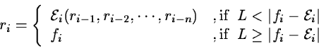
Figure 2.1:
A dark current CCD exposure with cosmic ray events which
are removed with non-linear filters.
(A) original, (B) 5*5 median filter, (C) 5*1 median filter,
and (D) 5*1 recursive filter.
 |
The main advantage of this filter type, compared to the median filter,
is its capability to remove artifacts larger than its own size.
Figure 2.1 shows a CCD dark current exposure with
cosmic ray events. It can be seen that all artifacts can be removed
using either a large median filter or a recursive filter while small
median filters are unable to remove the larger events. When real
features are present such as spectra in Figure 2.2 the
non-linear filters may modify spectral lines.
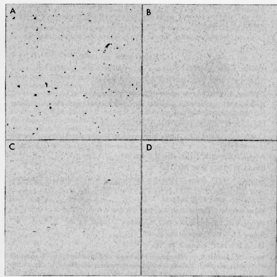
Figure 2.2:
Removal of cosmic ray events on a CCD spectral exposure with
different techniques: (A) original, (B)
 median filter,
(C)
median filter,
(C)
 recursive filter and (D) stack comparison.
 |
When more than two images of the same region are available, it is
possible to compare the stack of pixels from the different exposures.
The frames must be aligned and intensity calibrated before a
comparison can be performed. Artifacts become more difficult to
detect if an alignment, hence rebinning, is needed due to its
smoothing effect. Thus, the stacking technique is best suited for
removing cosmic ray events and electronic disturbances. Statistical
weights must also be assigned to the individual images depending on
exposure and signal-to-noise ratio. Outliers in the stack of pixel
values are rejected either by comparing them to the median or by
applying
 -clipping techniques (Goad, 1980). The
resulting frame is then the mean of the remaining values. A set of
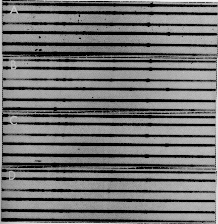
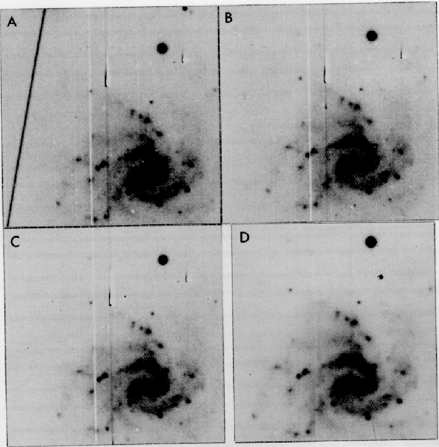
CCD images of the galaxy A0526-16 are shown in Figure 2.3
including the resulting stacked image. By having different origins of
the galaxy in the exposures the chip artifacts could also be removed.
For comparison with non-linear filter techniques,
Figure 2.2D shows removal of cosmic ray events from
the spectral frame discussed above.
-clipping techniques (Goad, 1980). The
resulting frame is then the mean of the remaining values. A set of
CCD images of the galaxy A0526-16 are shown in Figure 2.3
including the resulting stacked image. By having different origins of
the galaxy in the exposures the chip artifacts could also be removed.
For comparison with non-linear filter techniques,
Figure 2.2D shows removal of cosmic ray events from
the spectral frame discussed above.
Figure 2.3:
Removal of artifacts on CCD exposures (A,B,C) of the galaxy
A0526-16 by stacking the frames yielding the combined image (D).
 |
Next: Response Calibration
Up: Raw to Calibrated Data
Previous: Raw to Calibrated Data
Petra Nass
1999-06-15